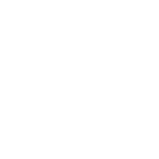

Bearing the Load, Reliably, Cost-Effectively!
Shafts in an IC engine (camshafts, crankshafts, wrist pins) typically rotate inside a plain bearing. They are preferred over roller or ball bearings due to:
They can better withstand the shocks and pulsating forces resulting from combustion events, engine vibrations, inertial forces etc.
Since they are typically manufactured as half bearing shells, they can be easily installed around the shafts, one half going around each side.
By design, these bearings are thin-walled, hence can be packed easily into the increasingly compact modern engines, in spaces where fitting a roller or ball bearing would be next to impossible.
Since plain bearings lack any moving parts or assembly they are much more tolerant to grime and contaminants floating in the engine oil.
Due to the highly scalable manufacturing process, plain bearings are typically much less expensive than rolling bearings.
Since these bearings require a constant oil film between them and the shaft, their consumption of oil is much higher than rolling bearings. This is addressed by incorporating an elaborate lubricating oil system inside the engine.
Size Range ofAutoGRACE® brand Engine Bearings
| SPECIFICATION | FROM | TO |
|---|---|---|
| Connecting Rod Big End Bearing | 25 | 200 |
| Crankshaft Main Bearings | 30 | 250 |
| Camshaft / Rocker Lever / Con Rod Small End Bushings | 15 | 130 |
| Thrust Washers | 40 | 225 |
Additionally, all bearings and bushings are available in following wall thicknesses:
The increase in wall thickness is achieved by decreasing the inner diameter of the bearing. The outer diameter remains same as a STD bearing since an oversize bearing also has to fit inside the same housing as a standard bearing. Due to wear and tear the journal of its mating shaft decreases in diameter. To compensate for this loss of material, an oversize bearing is installed.
Garima Global supplies components for a wide variety of on-road, off-road, industrial and stationary applications such as: automotive (light duty) and light commercial, trucks (heavy duty), tractors (agricultural), earthmoving and construction machinery, generators, irrigation pumps, and defence / special purpose vehicles.
The brands for which we manufacture and export aftermarket products are Caterpillar, Chevrolet, Chrysler, Citroen, Cummins, Daewoo, DAF, Daihatsu, Detroit Diesel, Deutz, Fiat, Ford, Hino, Honda, Hyundai, International, Isuzu, Iveco, John Deere, Kamaz, Kia, Komatsu, Kubota, Land Rover, Leyland, Lister Petter, Lombardini, Mack, Mahindra, MAN, Massey Ferguson, Mazda, Mercedes Benz, Mitsubishi, Navistar, Nissan, Onan, Perkins, Peugeot, Renault, Scania, Suzuki, Tata, Tatra, Toyota, Ursus, UTB, Volvo, Yanmar and Zetor, amongst others.
Garima Global also export parts for air-brake compressors like Wabco, Bendix, Knorr, Cummins, Clayton Dewandre, Mercedes, Midland etc.
Garima Global has developed an extensive range of components for engine, braking, transmission, suspension, steering, chassis, electrical, lighting and other automotive sub-systems. To assist our customers with choosing the right product for their requirements we have published comprehensive catalogs with engine / vehicle models, interchange with references of OEMs and other popular aftermarket brands, fitment dimensions and other technical data. We strongly encourage you to contact us with your specific requirements so that we can email you the relevant catalogs, and we look forward to starting a mutually beneficial business relationship with you soon!
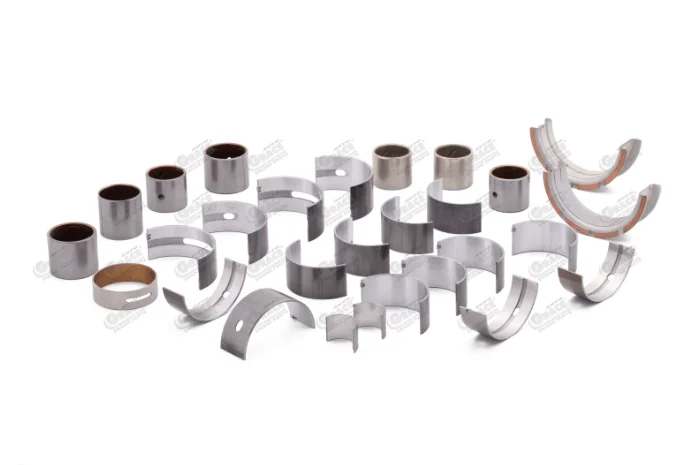
Engine bearings main be classified based on the type of loading they are subject to, their application and materials used to manufacture them.
Bearings like connecting rod big end bearings, most of the crankshaft main bearings, camshaft bearings and conrod small end bushes keep their shaft centred on its longitudinal axis. This is achieved by generating a film of lubricating oil in the space between the bearing and its mating journal. The combustion and inertial forces shift the centreline of the shafts, for example during power stroke the crankshaft is pushed downward, exerting extreme pressure on the lower shells of the main bearings.
Property of the lubricating oil is that its viscosity increases exponentially when subject to extreme pressures. This balances the external forces and keeps the mating surfaces from coming into contact with each other, thus achieving a perfectly lubricated rotational movement.
Typically thrust washers and flanged main bearings are examples of axial bearings used to arrest the longitudinal movement of shafts caused by, for example, engagement of the clutch or acceleration shock.
AutoGRACE® brand connecting rod bearings, main bearings, thrust washers and bushings are manufactured by leading manufacturers of engine bearings in India to provide relentless reliability and durability.
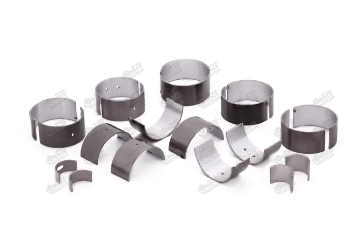
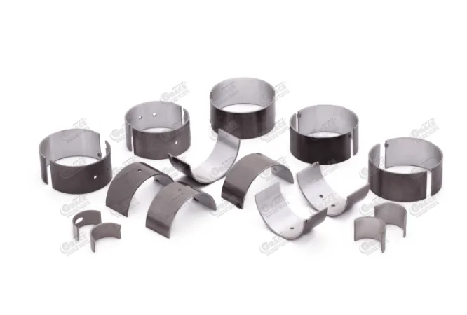
The big end of the connecting rod is cut or fractured into 2 halves (the cap and the rod) and the two conrod bearing shells fit into each half. The total circumference of the two bearing shells is slightly more than the big end housing diameter. This extra length is called the crush height of the bearing, and the two halves are literally “crushed” tightly into their place by bolting the cap of the conrod on to its body.
To further secure the bearing shells against lateral movement, small notches are cut into the big end housing at the parting plane, with mating projections stamped into the bearing shells.

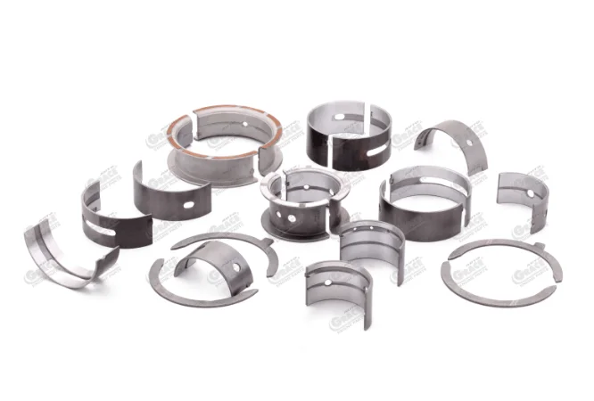
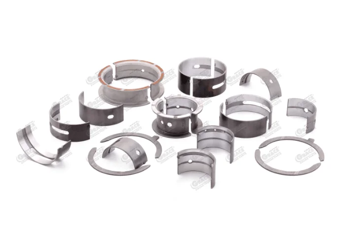
Main bearings look very similar to big end bearings however they may have tri-metal material to withstand the high combustion and momentum loads. The upper bearing shell may have an oil hole drilled into it which aligns with the lubricating oil channel cast into the engine block, through which oil is replenished to form a lubricating layer between the bearing and the crankshaft. Additionally an oil channel may be provided along the inner surface of the bearing to act as a reservoir of oil.
Some of the main bearing pairs are flanged, to integrate the function of a thrust washer and arrest the longitudinal movement of the crankshaft.
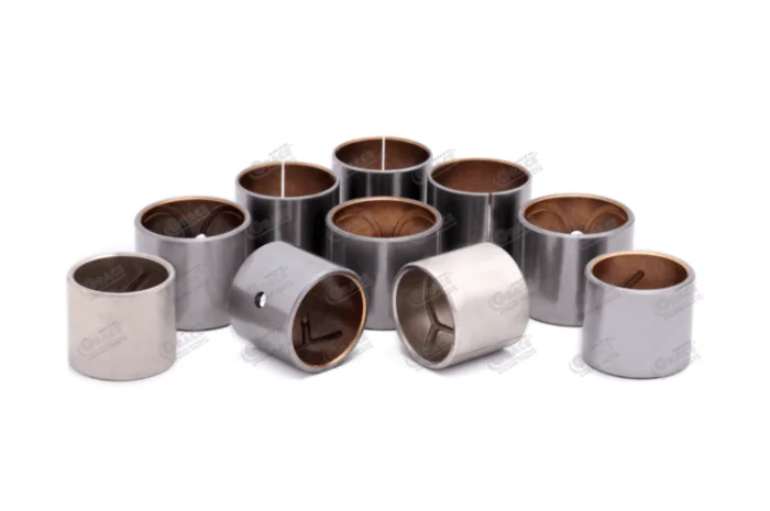
These are used in many locations, such as camshaft bushings, rocker lever bushings, connecting rod small end bushings etc. The material grade is selected depending on whether the range of motion is oscillating (for example, in rocker arm levers) or sliding (e.g. camshafts, con rods).
In heavy duty engines where none of the main bearings have an integrated flange, thrust washers are used to stabilize longitudinal motion of the camshaft.
Bearings and bushings are made by first overlaying the bearing material on a steel back. This strip is then cut and bent into shape as per size requirements. Many of our customers source these high-quality and cost effective strips from us with the bearing material overlay and then cut the strips as per requirements in their facilities to serve their customers with minimum lead time.
In industrial engines or in passenger cars with slow running camshafts, solid bearings made of hard bronze (CuPb15Sn7) or AlSn6 prove to be the most cost effective. They do not have any steel backing shell.
LEAD BASED WHITE METAL BABBIT
| ELEMENT | SAE 14 PbSb15Sn10 |
SAE 15 PbSb15SnAs |
|---|---|---|
| Silicon (%) | - | - |
| Nickel (%) | 0.05-0.15 | - |
| Iron (%) | - | - |
| Aluminum (%) | - | - |
| Copper (%) | ||
| (%) | 0.80-1.20 | 0.60 MAX |
| Tin (%) | 8.00-10.00 | 0.90-1.25 |
| Antimony (%) | 13.00-15.00 | 14.50-15.50 |
| Arsenic (%) | 0.40-0.70 | 0.80-1.20 |
| Lead (%) | BAL | BAL |
| (%) |
TIN BASED WHITE METAL BABBIT
| ELEMENT | SAE 12 SnSb8Cu4 |
|---|---|
| Silicon (%) | - |
| Nickel (%) | - |
| Iron (%) | - |
| Aluminum (%) | - |
| Copper (%) | 2.50-3.50 |
| Tin (%) | BAL |
| Antimony (%) | 6.50-7.50 |
| Arsenic (%) | - |
| Lead (%) | 0.35 MAX |
| Zinc (%) | - |
A steel shell (SAE 1008 / 1010) is coated with a babbit material – AlSn (aluminium-tin) alloys or CuPb (copper-lead) alloys, also known as leaded-bronze alloys. Since leaded bronze is susceptible to corrosive attack by sulphur and chlorine, aluminium-tin alloys are preferred in engines with heavy oil and gas-fired engines. Thus, AlSn alloys are today the most widely used material in big end and main bearings. However, aluminium-tin alloys are not very suitable for heavily loaded oscillating motions, for example at the small end of the connecting rod or the rocker arm. Copper based alloys continue to be the most preferred material for such applications.
LAYER 1: STEEL BACKING
| ELEMENT | SAE 1008 DIN 1.0204 AISI 1008 |
SAE 1010 DIN 1.0032 AISI 1010 |
|---|---|---|
| Carbon (%) | 0.10 MAX | 0.05 – 0.13 |
| Silicon (%) | 0.05 MAX | 0.05 MAX |
| Manganese (%) | 0.30 – 0.50 | 0.55 MAX |
| Phosphorus (%) | 0.04 MAX | 0.04 MAX |
LAYER 2: COPPER LEAD (CuPb)
| ELEMENT | SAE 49 CuPb24Sn |
SAE 792 CuPb10Sn10 |
SAE 793 CuPb9Sn5 |
SAE 794 CuPb24Sn4 |
|---|---|---|---|---|
| PROCESS | CAST / SINTERED | CAST / SINTERED | CAST | CAST / SINTERED |
| Nickel (%) | - | 0.50 MAX | 2.00 MAX | - |
| Copper (%) | BAL | BAL | BAL | BAL |
| Tin (%) | 1.75-2.75 | 9.00-11.00 | 4.00-6.00 | 2.00-4.00 |
| Antimony (%) | - | 0.50 MAX | 0.50 MAX | - |
| Arsenic (%) | - | - | - | - |
| Lead (%) | 21.00-27.00 | 9.00-11.00 | 8.00-10.00 | 23.00-27.00 |
| Zinc (%) | - | 0.75 MAX | 2.00 MAX | - |
LAYER 2: ALUMINIUM TIN (AlSn)
| ELEMENT | SAE 770 AlSn6Cu |
SAE 783 AlSn20Cu |
|---|---|---|
| Silicon (%) | 0.70 MAX | 0.50 MAX |
| Nickel (%) | 0.70-1.30 | - |
| Iron (%) | 0.70 MAX | 0.50 MAX |
| Aluminum (%) | BAL | BAL |
| Copper (%) | 0.70-1.30 | 0.70-1.30 |
| Tin (%) | 5.50-7.50 | 17.50-22.50 |
Tri-metal bearings represent a cost-effective and higher performance combination suitable for con rod big end bearings and main bearings. A steel shell is coated with leaded bronze / copper-lead alloy, on top of which PbSnCu overlay is electroplated. In heavy duty engines, the middle layer may be of AlZn4.5 material with PbSn16Cu2 overlay. Major limitation of these bearings is that once the 0.015-0.030 mm thick overlay wears off, bearing performance degrades rapidly.
LAYER 3: OVERLAY - LEADED
| ELEMENT | SAE 191 PbSn10 |
SAE 192 PbSn10Cu2 |
|---|---|---|
| Copper (%) | - | 2.00-3.00 |
| Tin (%) | 8.00-12.00 | 8.00-12.00 |
| Lead (%) | BAL | BAL |
Sputter bearings represent a fully matured bearing technology and can handle extreme loadings of modern engines with high energy density, especially direct-injection diesel engines. A steel back may or may not be coated with an intermediate leaded-bronze material, on which AlSn20 is vacuum coated. Due to the complex process, their cost may be 5-8 times that of an equivalent tri-metal bearing. Hence they are frequently used in combination with tri-metal bearings, with the shell subjected to heavy loading being a sputter bearing and the other half-shell subjected to less loading being a tri-metal bearing.
Bearings and bushings are frequently coating with tin flash to protect against corrosion during transit / storage. This layer wears off very rapidly once they are installed and engine is operated. The melting of tin may assist in gradual wear and seating of the shafts with the bearing.
Below table presents a summary of the various combinations in materials of engine bearings and the suitable applications for each.
LAYER 3: OVERLAY - LEADED
| Bearing | Backing Shell | Bearing Materia | Overlay | Primary use |
|---|---|---|---|---|
| Solid Bearing | None | CuPb15Sn7 | None | Wristpin bushings |
| AISn6 | Thrust washers, camshaft bearings | |||
| Bi-Metal Bearing | Steel | CuPb10Sn10 CuPb15Sn7 | None | Wristpin bushings, rocker arm bushings |
| AlSn6 | Thrust washers, camshaft bearings | |||
| AlSn20 | Main bearings, conrod bearings | |||
| SnSb12Cu | Camshaft bearings | |||
| Tri-Metal Bearing | Steel | CuPb10Sn10 | PbSnCu | Large wristpin bushings |
| CuPb20Sn2 | PbSn16Cu | Conrod bearing, main bearing | ||
| PbSn10Cu | ||||
| PbSn10 | ||||
| PbSn10 ceramic | ||||
| SnSb7 | ||||
| CuPb30 | ||||
| AlZn4.5 | PbSn16Cu2 | Conrod bearing | ||
| Sputter Bearing | Steel | CuPb20Sn2 | AlSn20 | Conrod bearing |
| CuPb10Sn10 |
Source: Basshuysen, R. & Schafer, F. (2004). Internal Combustion Engine Handbook: Basics, Components, Systems, and Perspectives. SAE International.
The leaded bronze / copper-lead alloy may be coated on to the steel back either by sintering process or casting process. Casting process is more fault tolerant since process defects during sintering cause voids and pores which reduce the strength of the bearing material.
The powder for sintering copper alloy is prepared by atomization of a melt of the alloy through the following stages:
The steel strip is uncoiled from its rolled form.
The steel strip is passed through rollers or similar equipment to straighten it.
The strip is immersed in a hot alkaline solution and mechanically cleaned by rotating steel wire cylindrical brushes.
The strip surface is abraded by a rotating endless belt.
The powder of the copper alloy is poured over the steel surface with pre-calculated thickness. The calculation takes into account two factors: a) the ratio between the densities of the powder and the sintered alloy, and b) elongation of the strip as a result of Rolling.
The process is performed in a long (about 33ft/10m) sleeve-type continuous sintering furnace. The sintering temperature is within the range of 1515-1615°F (824-880°C) depending on the alloy composition. The atmosphere in the furnace is reducing: it consists of a mixture of Hydrogen and Nitrogen. During the sintering process atmospheric hydrogen converts the oxides of copper (and other metals) on the surface of each powder particle into the metallic state (CuO + H2 = Cu + H2O). The particles then physically join (weld) to each other and to the steel strip due to the mutual diffusion of their atoms.
After sintering stage density of the alloy is higher than in the powder state but it is still 20-30% lower than in the fully compacted state. The pores between the joined particles are closed in the compaction stage when the strip passes through a rolling mill.
This stage is performed in order to set the physical joining (welding) between the surfaces of the pores mechanically closed in the compaction stage. Re-sintering is conducted in a sintering furnace similar to that of the sintering stage. Parameters of the process are also similar to those of sintering. As a result of re-sintering sound (no porosity) sinter structure of the copper alloy forms. The second phase (lead, bismuth) is homogeneously distributed throughout the copper based matrix in form of small particles (0.001-0.002”/25-50 μm) located between the copper grains.
This stage is performed in order to strengthen (strain harden) both the steel back and the sintered copper alloy.
The bi-metal strip is then recoiled onto a roller for stamping and cutting to size.
The steel strip is uncoiled from its rolled form.
The steel strip is passed through rollers or similar equipment to straighten it.
The strip is immersed in a hot alkaline solution and mechanically cleaned by rotating steel wire cylindrical brushes.
The strip edges are roll formed producing a shallow trough.
The steel strip is heated to about 1830°F (1000°C) in a reducing atmosphere preventing oxidation.
The melt heated to 2280°F (1250°C) is poured onto the strip surface. The shaped edges prevent the melt from overflowing.
The strip is sprinkled by water streams, which cools it down and causes solidification of the copper alloy. The resulting cast structure of the copper alloy presents copper dendrites oriented perpendicular to the steel surface with the second phase particles (lead, bismuth) located between the dendrite arms.
The strip edges are slit.
The strip surfaces are polished.
The bi-metal strip is then recoiled onto a roller for stamping and cutting to size.
Dr. Kopeliovich, D., 2021. Manufacturing bi-metal strips for copper bearings [SubsTech]. [online] Substech.com. Available at: https://www.substech.com/dokuwiki/doku.php?id=manufacturing_bi-metal_strips_for_copper_bearings
In these bearings, an aluminium based alloy is bonded onto to the steel back by cold rolling a continuously cast strip of aluminium bearing alloy together with a strip of low carbon steel.
The most popular method to avoid the adverse effect of tin on adhesion between the bonded strips is cladding the aluminum strip with a bonding layer of pure aluminum (technically pure alloy with 99.5-99.7% Al, eg. 1060) prior to steel backing.
Most methods of continuous casting of aluminium based bearing alloys result in internal stresses therefore the castings should be annealed prior to cladding.
Prior to the cladding operation the coiled strip of pure aluminum is degreased, mechanically cleaned and brushed in a cleaning line where the aluminum strip passes through a solvent degreaser, vapors of which dissolve oils (commonly protection oils) on the strip surface. Degreased strip is cleaned by rotating steel wire circular brushes and re-coiled on drums. Only the surface which is to be bonded to the alloy strip is brushed.
Clean and annealed cast strip is uncoiled, straightened and brushed from both sides by steel wire circular brushes, which remove oxide film, residuals of burnt oil and other foreign substances. Simultaneously two strips of pure aluminum are also un-coiled. Three strips enter a two-high rolling mill where they adhere to each other as a result of Solid State Welding (SSW). The pressure necessary for achievement of bonding is obtained at relatively high thickness reduction for on-pass rolling operation. The second rolling pass with lower thickness reduction provides stable bonding with the value of adhesion stress close to the tensile strength of aluminum. The strip of aluminum alloy clad with pure aluminum is then cold rolled to the final thickness for several rolling passes through reverse rolling mills prior to bonding with steel back. Finally, the strip is cut by a slitter in order to remove defective edges and produce the required strip width.
Coil of a steel strip is installed on the uncoiler of the bonding line. The steel strip is uncoiled straightened, cleaned by circular rotating brushes in the washing unit using a hot alkaline solution and then grinded by rotating abrasive belts.
In parallel the aluminum alloy strip is uncoiled and brushed by steel wire rotating circular brushes (only the surface, which is to be bonded to the steel strip is brushed). The two strips enter a four-high rolling mill where they adhere to each other as a result of Solid State Welding (SSW). The pressure necessary for achievement of bonding is obtained at relatively high thickness reduction for on-pass rolling operation.
Aluminum bearing alloy on the bonded bi-metal strips has internal stresses and the stress on the boundary between the aluminum and steel strip. The stresses may lead to the bearing’s failure therefore stress relief operation of the bonded strips is necessary. In addition to this the aluminum grains and tin plates adjacent to the grains surfaces are elongated along the Rolling direction. Such microstructure is anisotropic with low strength in the direction perpendicular to the rolling direction. Isotropic microstructure may be obtained as a result of recrystallization. Full annealing of the aluminum alloy bonded to steel strip provides both stress-relief and recrystallization. Full annealing also changes the tin configuration, which converts into reticular (network) structure.
The bi-metal coil after annealing heat treatment is installed onto the inspection line where the strip is cleaned, checked, oiled and recoiled. The strip is uncoiled then the tin “sweating” at the edges is removed, after which the steel and aluminum surfaces are brushed by rotating circular steel brushes. Adhesion is tested by chisel and then the strip thickness is checked by a continuous thickness measurement appliance. The defective parts are marked, the strip is coated by an anti-corrosion oil and recoiled.
Dr. Kopeliovich, D., 2021. Manufacturing bi-metal strips for aluminum bearings [SubsTech]. [online] Substech.com. Available at: https://www.substech.com/dokuwiki/doku.php?id=manufacturing_bi-metal_strips_for_aluminum_bearings
Sputter overlays are deposited by Physical Vapor Deposition (PVD) process, utilizing argon ions for bombarding a cathodically connected target made of the coating material (normally Al20Sn or Al40Sn).
Of the vacuum chamber and introduction of argon gas.
Of argon, which converts to plasma state: positively charged argon ions.
The substrate (bearing) surface acts as a cathode and the positive argon ions bombard the substrate surface and clean it. This provides good adhesion of the deposit to the bearing surface.
The cathode now is a target made of Ni/NiCr. The argon ions bombard the target knocking the atoms of nickel (nickel and chromium) out from the target. The atoms moving off the target meet the substrate surface and stick to it. Thickness of the diffusion layer is 0.00004”-0.00008” (1-2 µm).
At this stage the cathode is a target made of aluminum-tin alloy (Al20Sn or Al40Sn). Atoms of the target are knocked out by the high energy ions and deposit on the substrate surface forming AlSn overlay.
Sputtering method provide extremely homogeneous distribution of tin within the aluminum matrix. Hardness of aluminum-tin sputter material is about 90 HV, which is three times higher than hardness of aluminum-tin alloy prepared by conventional methods (casting). Cast copper based bearings or high strength aluminum based bearings are commonly plated by sputter overlays. Load carrying capacity of sputter bearings is highest of all bearing materials: 14500-17400 psi (100-120 MPa).
The disadvantages of sputter bearings: high production cost (slow deposition process) and poor soft anti-friction properties (compatibility, conformability, embedability). Improvement of anti-friction properties and cost reduction are achieved by a combination of a sputter bearing shell in the high load position (conrod) with a common tri-metal bearing shell in the less loaded position (cap). Sputter bearings are mainly used as connecting rod bearings in highly loaded diesel engines with direct fuel injection system.
Dr. Kopeliovich, D., 2021. Sputter bearing overlays [SubsTech]. [online] Substech.com. Available at: https://www.substech.com/dokuwiki/doku.php?id=sputter_bearing_overlays
AutoGRACE® brand engine bearings are manufactured by one of the above processes as per requirements of the applications they are built for, by the leading manufacturers of connecting rod big end bearings, crankshaft main bearings, thrust washers, connecting rod small end bushings, camshaft bushes, rocker arm bushings and other engine bearings and bushings in India.
Start the
conversation.
Every beautiful relationship starts with a simple hello. So let’s chat. It might just be the start of something memorable.